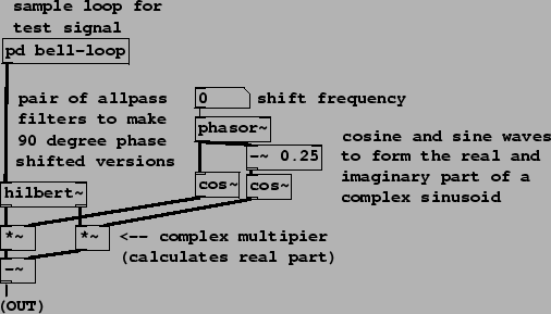
As described in Section 8.4.3, a pair of all-pass filters
can be constructed to give roughly ![]() phase difference for positive
frequencies and
phase difference for positive
frequencies and ![]() for negative ones. The design of these pairs is
beyond the scope of this discussion (see, for instance, [Reg93]) but
Pd does provide an abstraction, hilbert~, to do this. Example
H09.ssb.modulation.pd, shown in Figure 8.31, demonstrates how to use the
hilbert~ abstraction to do signal sideband modulation. The
Hilbert transform dates to the analog era [Str95, pp.129-132].
for negative ones. The design of these pairs is
beyond the scope of this discussion (see, for instance, [Reg93]) but
Pd does provide an abstraction, hilbert~, to do this. Example
H09.ssb.modulation.pd, shown in Figure 8.31, demonstrates how to use the
hilbert~ abstraction to do signal sideband modulation. The
Hilbert transform dates to the analog era [Str95, pp.129-132].
The two outputs of hilbert~, considered as the real and imaginary parts of a complex-valued signal, are multiplied by a complex sinusoid (at right in the figure), and the real part is output. The components of the resulting signal are those of the input shifted by a (positive or negative) frequency specified in the number box.